Physics Practical: Electric Current, Potential Difference, and Resistance
Physics Practical explores fundamental concepts in electricity, including electric current, potential difference, and resistance. It provides detailed experiments to study Ohm’s Law and the behavior of resistors in series and parallel circuits. This practical guide is essential for students in physics courses, offering hands-on activities to reinforce theoretical knowledge. It includes step-by-step methods, observations, and calculations to help students understand the principles of electricity. Ideal for high school and college-level physics students preparing for exams.
Key Points
Explains electric current and its measurement in amperes.
Covers experiments on potential difference and resistance using Ohm’s Law.
Includes practical applications of resistors in series and parallel circuits.
Provides step-by-step methods for conducting physics experiments.
This link leads to an external site. We do not know or endorse its content, and are not responsible for its safety. Click the link to proceed only if you trust this site.
Physics Investigatory Project: Transformer Voltage RatioLab Report
PDFNotes
AQA GCSE Physics Topic 2: Electricity NotesNotes
PDF
AP Physics C Practice Workbook Book 2 Electricity and Magnetism
PDF
AP Physics C: Electricity and Magnetism Practice Exam
PDF
AP Physics C Electricity and Magnetism Practice Test 1
PDF
AP Physics C Electricity and Magnetism Course Description
PDF
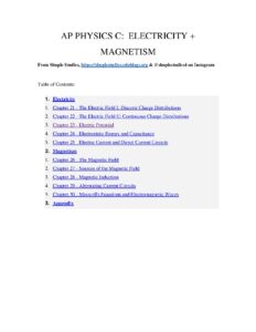
AP Physics C Electricity and Magnetism Study Guide
PDF
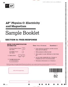
AP Physics C Electricity and Magnetism Sample Free Response
PDF
AP Or Concurrent Enrollment | What’s The Difference?
PDFLab Report
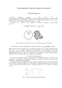
Fractals and Fractal Dimension: An In-Depth StudyLab Report
PDFLab Report
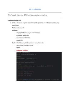
Java Technology Lab 12Lab Report
PDFLab Report
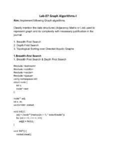
Graph Algorithms Lab 7 – DAALab Report
FAQs
What is the definition of electric current in this lab report?
Electric current is defined as the flow of free electrons in a definite direction through a conductor. The rate of flow of charge through a conductor is called electric current, measured in amperes (A). It is quantified using the formula Current (I) = Charge (q) / Time (t).
How is potential difference defined in the document?
Potential difference, or p.d., is defined as the amount of work done when a unit charge flows from one point to another in an electric circuit. The SI unit of potential difference is the volt (V). The maximum potential difference that can exist between two terminals of a cell, when no current is drawn, is referred to as electromotive force (e.m.f.).
What does Ohm's Law state according to the lab report?
Ohm's Law states that the electric current flowing through a conductor is directly proportional to the potential difference across its ends, provided that physical conditions such as temperature and pressure remain constant. This relationship can be expressed mathematically as V = I × R, where V is the potential difference, I is the current, and R is the resistance.
What materials are required for the experiment on electric current and resistance?
The materials required for the experiment include 10 pieces of thick insulated copper wire with bare ends, sandpaper, a one-way key, a dry cell with positive and negative terminals, an ammeter (0-1.5 A range), a voltmeter (0-1.5 V range), a rheostat (10 ohm), and a resistor of about 2 ohms resistance.
How do you calculate the resistance from the V-I graph?
To calculate the resistance from the V-I graph, you plot the potential difference (V) on the y-axis and the current (I) on the x-axis. The graph will be a straight line, and the resistance can be determined by calculating the slope of this line, represented by the formula R = ΔV / ΔI, where ΔV is the change in potential difference and ΔI is the change in current.
What precautions should be taken during the experiment?
Precautions include correcting any zero error in the ammeter and voltmeter, ensuring that connections are neat and tight, and using a low resistance rheostat (not more than 10 ohms). Additionally, the positive terminals of the ammeter and voltmeter should be connected to the positive terminal of the cell, and the current should be kept low to avoid heating the resistor.
What is the significance of the slope of the V-I graph?
The slope of the V-I graph represents the magnitude of resistance in the circuit. Since the graph is a straight line, it confirms that the potential difference is directly proportional to the current flowing in the circuit, thereby verifying Ohm's Law. A constant slope indicates that the resistance remains unchanged under the experimental conditions.