BIT103 Digital Logic focuses on essential concepts in digital logic design, including combinational and sequential circuits. This document serves as a comprehensive guide for students enrolled in the Bachelor of Information Technology program at Tribhuvan University. Key topics include decoders, ring counters, and Boolean algebra. The content is structured to aid in exam preparation, featuring long and short answer questions, practical circuit designs, and truth tables. Ideal for first-year students looking to strengthen their understanding of digital logic principles.

Key Points

  • Explains the design and function of decoders, including BCD to Decimal conversion.
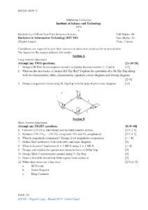
  • Covers combinational logic circuits and their applications in digital systems.
  • Details the operation of ring counters with timing diagrams and sequences.
  • Includes practical exercises on converting binary numbers to decimal and hexadecimal.
Sewang Rai.2
2 pages
Language:English
Type:Past Paper
Sewang Rai.2
2 pages
Language:English
Type:Past Paper
168
/ 2
BIT103-2077
Tribhuvan University
Institute of Science and Technology
2077
Bachelor Level/First Year/First Semester/Science Full Marks: 60
Bachelors in Information Technology (BIT 103) Pass Marks: 24
(Digital Logic) Time: 3 Hours
Candidates are required to give their answers in their own words as for as practicable.
The figures in the margin indicate full marks.
Section A
Long Answer Questions
Attempt any TWO questions. [2x10=20]
1. What is decoder? Design BCD to Decimal Decoder with truth table and logic diagram.
[2+8]
2. Define combinational logic circuit. Design a combinational circuit whose input is a
four-bit number and output is 2's complement of the input number. [2+8]
3. What is ring counter? Explain ring counter with diagram, timing sequence and timing
diagram. [2+8]
Section B
Short Answer Questions
Attempt any EIGHT questions. [8x5=40]
4. Convert (1011.110) into decimal and hexadecimal. [2.5+2.5]
5. Substract (1011.11 - 1010.10) using 2's and l's complement. [2.5+2.5]
6. Express the given function in sum of minterms.
F = y’z + wxy’ + wzx’ + w’x’z’ [5]
7. Simplify the Boolean function using don't care conditions d, In sum of products and
product of sums form. [2.5+2.5]
F(A, B, C, D) = 𝜋(1,3,7,8,12) and 𝜋d(5,10,13,14)
8. Implement a full subtractor with two half subtractors and one OR Gate. [5]
9. Define SR latch with logic diagram and truth table. [1+4]
10. Compare the logic of synchronous counter and ripple counter. [2+3]
11. Define shift register with its types. [5]
IOST, TU
BIT103 - Digital Logic - Board 2077 - bitinfoNepal
BIT103-2077
12. Write short notes on: [2x2.5=5]
a) Parity generator
b) State diagram
IOST, TU
BIT103 - Digital Logic - Board 2077 - bitinfoNepal
/ 2
End of Document
168

FAQs

What is a decoder and how does a BCD to Decimal Decoder work?
A decoder is a combinational logic circuit that converts binary information from n input lines to a maximum of 2^n unique output lines. The BCD to Decimal Decoder specifically takes Binary Coded Decimal (BCD) input and produces a corresponding decimal output. The document includes a truth table and a logic diagram illustrating this conversion, detailing how each BCD input corresponds to a specific decimal output.
What are the differences between synchronous and ripple counters?
Synchronous counters and ripple counters differ primarily in how they respond to clock signals. In synchronous counters, all flip-flops are triggered simultaneously by a common clock signal, leading to faster operation. In contrast, ripple counters trigger each flip-flop sequentially, which can introduce delays as the output of one flip-flop serves as the clock input for the next. The document compares these two types of counters, highlighting their operational efficiencies and timing characteristics.
How do you implement a full subtractor using half subtractors?
To implement a full subtractor using two half subtractors and one OR gate, the first half subtractor takes the minuend and subtrahend as inputs to produce the difference and borrow. The second half subtractor then takes the output difference and the borrow from the first subtractor to produce the final difference. The OR gate combines the borrows from both half subtractors to yield the final borrow output. This method is detailed in the document, showcasing the logic behind the circuit design.
What is a ring counter and how does it operate?
A ring counter is a type of counter composed of flip-flops connected in a circular manner, where the output of the last flip-flop is fed back to the first. The document explains the operation of a ring counter with a diagram and timing sequence, illustrating how it cycles through a predetermined sequence of states. The timing diagram further clarifies the state transitions over time, demonstrating the counter's functionality.
What is the significance of a parity generator in digital circuits?
A parity generator is a crucial component in digital circuits used to ensure data integrity during transmission. It generates a parity bit that can be added to a data set, allowing the detection of errors by verifying whether the number of set bits is even or odd. The document provides a brief overview of parity generators, emphasizing their role in error detection mechanisms within digital communication systems.
How do you convert binary numbers to decimal and hexadecimal?
The conversion of binary numbers to decimal involves multiplying each bit by 2 raised to the power of its position and summing the results. For example, the document illustrates converting the binary number (1011.110) into its decimal equivalent. Similarly, the conversion to hexadecimal involves grouping the binary digits into sets of four and translating each group into its corresponding hexadecimal value, which is also detailed in the document.
What is a shift register and what are its types?
A shift register is a type of digital memory circuit used for storing and shifting data. The document outlines various types of shift registers, including serial-in serial-out (SISO), serial-in parallel-out (SIPO), parallel-in serial-out (PISO), and parallel-in parallel-out (PIPO). Each type serves different applications in data handling and processing, making shift registers versatile components in digital systems.