BIT103 Digital Logic focuses on fundamental concepts in digital logic design, including combinational circuits, flip-flops, and counters. This resource is essential for students pursuing a Bachelor in Information Technology at Tribhuvan University. It covers key topics such as race conditions in JK flip-flops and the implementation of functions using decoders and multiplexers. Ideal for first-year students, this guide provides a comprehensive overview of digital logic principles and practical applications.

Key Points

  • Explains combinational circuits with four inputs and one output.
  • Covers implementation of functions using decoders, multiplexers, and PLAs.
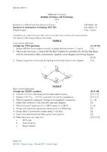
  • Discusses race conditions in JK flip-flops and methods to overcome them.
  • Details the design of Mod-3 synchronous counters and parallel-in parallel-out shift registers.
Sewang Rai.2
2 pages
Language:English
Type:Past Paper
Sewang Rai.2
2 pages
Language:English
Type:Past Paper
171
/ 2
BIT103-2078
Tribhuvan University
Institute of Science and Technology
2078
Bachelor Level/First Year/First Semester/Science Full Marks: 60
Bachelors in Information Technology (BIT 103) Pass Marks: 24
(Digital Logic) Time: 3 Hours
Candidates are required to give their answers in their own words as for as practicable.
The figures in the margin indicate full marks.
Section A
Long Answer Questions
Attempt any TWO questions. [2x10=20]
1. Design a combinational circuit with four inputs and one output. The output is equal to 1
when (i) all the inputs are equal to 1 or (ii) none of the inputs arc equal to 1 or (iii) an odd
number of inputs are equal to 1. [10]
2. Implement the following function: [10]
F = ∑(0,1,3,4,5,8,9,10,15) using
i) Decoder
ii) Multiplexer
iii) PLA
3. What do you mean by race condition in JK Flip Flop and mention the methods to
overcome it? Explain Master Slave Flip-flop using JK flip flop with logic circuit, truth
table and timing diagram. [3+7]
Section B
Short Answer Questions
Attempt any EIGHT questions. [8x5=40]
4. Convert (1011.110) into decimal and hexadecimal. [2.5+2.5]
5. Convert (51966.57)
10
into octal and hexadecimal number system. [2.5+2.5]
6. Subtract (111000.110)
2
(110100.101)
2
using both 2's and l's complement. [5]
7. State and prove De-Morgan's Theorems. [5]
8. Define Half-subtractor with truth table and logic diagram. [5]
IOST, TU
BIT103 - Digital Logic - Board 2078 - bitinfoNepal
BIT103-2078
9. What is decoder? Implement 8 x 1 MUX using 4 x 1 MUX. [1+4]
10. What is clocked RS flip-flop? Explain with logi:2 diagram and characteristic table. [1+4]
11. Design Mod-3 synchronous counter. [5]
12. Draw a Parallel-In Parallel-Out Shift register and explain it. [5]
13. Write short notes on: [2.5+2.5]
a. Binary parallel adder
b. Jonson counter
IOST, TU
BIT103 - Digital Logic - Board 2078 - bitinfoNepal
/ 2
End of Document
171

FAQs

What is the main purpose of designing a combinational circuit in BIT103?
The main purpose of designing a combinational circuit in BIT103 is to create a circuit with four inputs and one output, where the output is equal to 1 under specific conditions: when all inputs are 1, none of the inputs are 1, or when an odd number of inputs are equal to 1. This exercise helps students understand the principles of digital logic and the functionality of combinational circuits.
How can the function F = ∑(0,1,3,4,5,8,9,10,15) be implemented?
The function F can be implemented using various methods as outlined in the BIT103 document. Students are required to use a decoder, a multiplexer, and a programmable logic array (PLA) to realize this function. Each method provides a different approach to digital circuit design, emphasizing the versatility of implementing logical functions.
What is a race condition in a JK Flip Flop and how can it be overcome?
A race condition in a JK Flip Flop occurs when the inputs change state while the clock is transitioning, leading to unpredictable outputs. To overcome this issue, the document suggests using a Master-Slave Flip-Flop configuration. This design ensures that the inputs are stable during the clock transition, which prevents race conditions and provides reliable output.
What are De-Morgan's Theorems and how are they proven?
De-Morgan's Theorems state that the complement of a conjunction is equal to the disjunction of the complements and vice versa. The document provides a proof for these theorems, demonstrating their validity through logical equivalences and truth tables. Understanding these theorems is crucial for simplifying complex logical expressions in digital circuits.
What is the function of a Half-subtractor in digital logic?
A Half-subtractor is a combinational circuit that performs the subtraction of two binary digits. The document includes a truth table and a logic diagram for the Half-subtractor, illustrating its inputs and outputs. It is essential for understanding basic arithmetic operations in digital systems.
How is an 8 x 1 MUX implemented using a 4 x 1 MUX?
The document explains that an 8 x 1 multiplexer (MUX) can be implemented using two 4 x 1 MUXes. The first 4 x 1 MUX selects between the first four inputs, while the second one selects from the last four inputs. The outputs of both 4 x 1 MUXes are then combined using an additional selection line, demonstrating a practical approach to circuit design.
What is a clocked RS flip-flop and how is it characterized?
A clocked RS flip-flop is a type of flip-flop that changes its output state based on the input signals and the clock signal. The document provides a logic diagram and a characteristic table for the clocked RS flip-flop, detailing how it operates under different input conditions. This understanding is vital for students studying sequential circuits in digital logic.