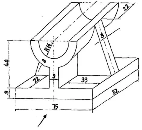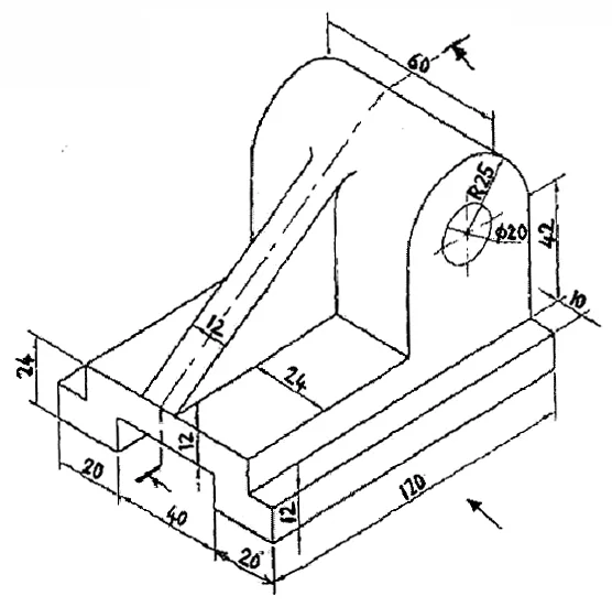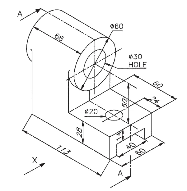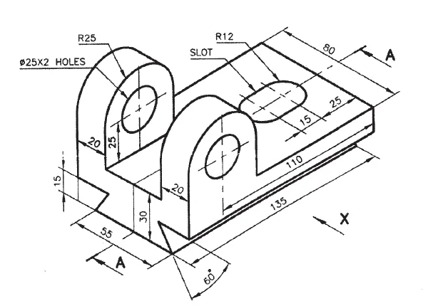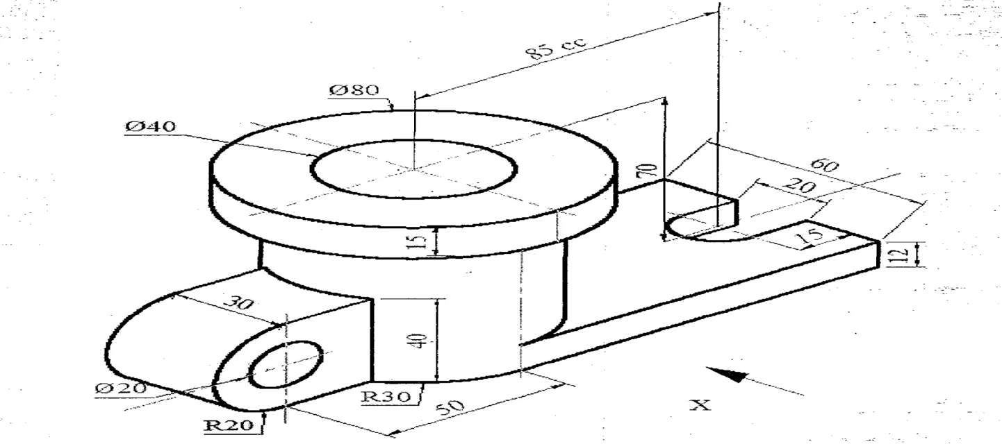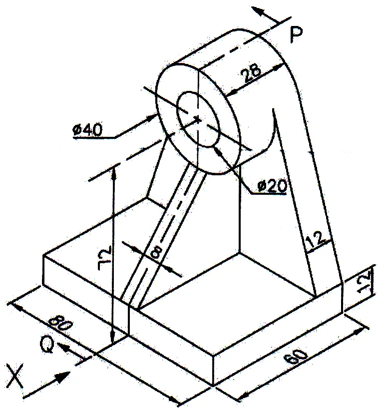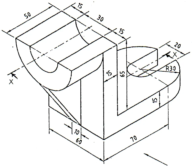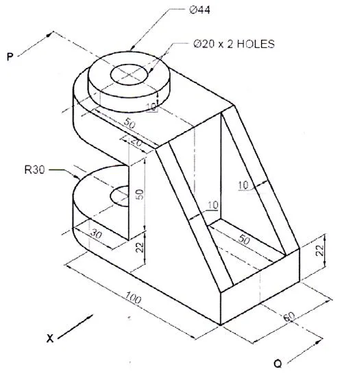
Engineering Graphics and Design Question Bank 1 serves as a comprehensive resource for students preparing for engineering exams. It includes a variety of questions focused on projection techniques, engineering curves, and orthographic projections. This question bank is ideal for engineering students seeking to enhance their understanding of graphical representation in engineering design. It covers essential topics such as projections of lines and planes, development of lateral surfaces, and isometric projections, making it a valuable study aid for exam preparation.

Key Points

  • Includes a variety of projection techniques for engineering graphics.
  • Covers engineering curves and their applications in design.
  • Features orthographic projections essential for engineering students.
  • Provides practice questions for effective exam preparation.
Bhagyshree Sonwane
15 pages
Language:English
Type:Textbook
Bhagyshree Sonwane
15 pages
Language:English
Type:Textbook
92
/ 15
CAYM EDUCATION TRUST’S
SIDDHANT COLLEGE OF ENGINEERING.
(Approved by All India Council for Technical Education (AICTE) New Delhi ,recognized by Government of
Maharashtra, Mumbai & Affiliated to the Savitribai Phule Pune University)
At. Post - Sudumbre, Tal. - Maval, Dist. - Pune, PIN - 412 109.
9923906993/9021977573 Fax No. 02114-661902
Website: - www.siddhantcoe.in E-mail:scoeadmiss[email protected]
Unit 01-Projection of Line (10 Marks - Q.1 or Q.2)
1. A line PQ 90 mm long, is inclined to H.P and V.P. at 34° and 30° respectively. Draw the
projections if point P is 25 mm above H.P. and point Q is 20 mm in front of V.P.
2. A Line AB resting in the first quadrant has its end A is 30mm above HP & in the V.P. End B is at
30mm in front of V.P. Draw the projection of line if, its elevation makes 39
0
inclination to H.P. &
plan makes 30
0
inclination to V.P.
3. A line AB of 90 mm long, having its endpoint A is on HP and 20 mm in front of VP. The plan
length of the line AB is 70 mm and makes an angle of 40
o
with XY. Draw the projections of line
AB. Find the inclination made by the line with HP and VP.
4. The end A of line AB is 20 mm above H.P. while its end B is 10 mm in front of V.P. Its plan and
Elevation makes an angle of 40
o
and 45
o
with XY respectively. Draw the projection of line, if the
distance between end projectors of line is 60 mm. find its true length & Inclination with H.P. &
V.P.
5. The point A of line AB is in H.P and 15 mm in front of V.P. Its front view and top view makes 51°
and 48° with H.P. and V.P. respectively. Draw the projections of line AB if projector distance
between end points of the line is 41 mm. Find its true length, true inclinations and locate its traces.
6. The Point M of Line MN is in the HP while its other end N is 50 mm above HP and 80 mm in front
of VP. The line is inclined to VP at an angle of 30
o
Draw the projection of line if its elevation
makes angle 29
o
with HP. Find true length of line and the inclination made by line with HP.
7. A line AB, 75 mm long is inclined at an angle of 35º to the V.P. Its end point ‘A’ is 20 mm above
the H.P. and 15 mm in front of the V.P. Plan length of the line is 50 mm. Draw the projections of
the line AB assuming it to be in first quadrant.
8. The point A of 65 mm line AB is in the HP and 15 mm in front of VP. The line is inclined to HP
& VP at 40
o
and 35
o
respectively. Draw the projection of line AB.
9. The distance between the end projectors of line AB is 60 mm. The end A is 25 mm above H.P. and
45 mm in front of V.P., while the other end B is 60 mm above H.P. and 15 mm in front of V.P.
Draw the projections and find the true length and also inclination of the line with H.P. and V.P.
10. Plan view and elevation view of a line AB, 70 mm long measures 55 mm and 60 mm respectively.
Draw its projections if end A is 15 mm above H.P. and 20 mm in front of V.P. Determine its
inclinations with H.P. and V.P.

CAYM EDUCATION TRUST’S
SIDDHANT COLLEGE OF ENGINEERING.
(Approved by All India Council for Technical Education (AICTE) New Delhi ,recognized by Government of
Maharashtra, Mumbai & Affiliated to the Savitribai Phule Pune University)
At. Post - Sudumbre, Tal. - Maval, Dist. - Pune, PIN - 412 109.
9923906993/9021977573 Fax No. 02114-661902
Website: - www.siddhantcoe.in E-mail:scoeadmiss[email protected]
Unit 02-Projection of Plane (10 Marks - Q.3 or Q.4)
1. A circular plate of diameter 60 mm is resting on H.P. It is then inclined to H.P. so that the point
opposite to resting points is 40 mm above H.P. Draw the projections if the plan of diameter line
passing through resting point makes 35° with XY. Find inclinations made by the plate with
reference planes.
2. A Hexagonal Plate ABCDEF of 35 mm size is resting on its corner F on the H.P. Draw the
projections of plate when the plate surface makes an angle of 35
o
to H.P. and plan of the FC make
an angle of 40
o
to V.P.
3. A circular plane lamina having diameter 60 mm is resting on one of its circumferential point in H.P.
in such a way that its plan appears as an ellipse having a major axis 60 mm long and minor axis is
40 mm. draw the projections, if the plan of minor axis makes an angle of 40
o
to the V.P.
4. A Pentagonal plate of 40 mm side is resting on HP on one of its sides such that the corner opposite
to it is 25 mm above HP. The side in HP makes an angle of 20
o
with VP. Draw its projection & find
inclination with HP & VP.
5. A regular pentagonal plate of 30 mm sides is resting on H.P. on one of its sides with its surface
inclined at 45º to HP. Draw its projections when the side in HP makes an angle of 30º with V.P.
6. A rhombus ABCD with diagonal AC =100 mm and BD =60 mm is resting on corner A in the
Horizontal plane. Its corner B is 25 mm above Horizontal plane. Draw the projections of the plane,
when top view of diagonal AC is inclined at an angle of 30o with the vertical plane.
7. A square lamina of sides 60 mm is resting on the H.P. on one corner. The lamina seen as a rhombus
in the top view, with one of its diagonals measuring 64 mm. The same diagonal makes an angle of
45
o
with the V.P. Draw the projections of the lamina and determine its angle with the H.P.
8. A rhombus of longer diagonal 60 mm and 40 mm is resting on the corner of a larger diagonal on the
H.P. such that the top view is a square of 40 mm diagonals. Draw is projection if the top view of a
larger diagonal makes an angle of 45
o
with the V.P.
9. An isosceles triangular plate of 50 mm base and 75 mm altitude appears as an equilateral triangle of
50 mm in top view. Draw the projection of a plate if its 50 mm long edge is on the H.P. and
inclined at 45
o
to the V.P. What is the inclination of a plate with the H.P. and V.P.?
10. A hexagonal plate base side 50 mm is resting on one of its corner with its side parallel to VP. Its
surface is inclined to HP that corner opposite to resting corner is 51 mm above HP. Draw the
projections if top view line is passing through resting corner and its opposite corner is inclined to
VP at 35
o
.
CAYM EDUCATION TRUST’S
SIDDHANT COLLEGE OF ENGINEERING.
(Approved by All India Council for Technical Education (AICTE) New Delhi ,recognized by Government of
Maharashtra, Mumbai & Affiliated to the Savitribai Phule Pune University)
At. Post - Sudumbre, Tal. - Maval, Dist. - Pune, PIN - 412 109.
9923906993/9021977573 Fax No. 02114-661902
Website: - www.siddhantcoe.in E-mail:scoeadmiss[email protected]
Unit 03-Engineering Curves & Development of Lateral Surface
(12 Marks - Q.5 a), b) or Q.6 a), b))
1. Draw the development of lateral surface of pentagonal prism resting on of base side 30 mm and
axis height 60 mm.
2. Draw a conic section when eccentricity ration is one. The distance between fixed line and focus is
50 mm; Name the curve give all necessary dimensions.
3. Draw the development of lateral surface of Hexagonal prism of base side 25 mm and axis height 65
mm.
4. Draw a cycloid of the rolling circle of diameter 55 mm along a straight line for one convolution and
consider the starting point is farthest from the ground.
5. Draw a curve traced out by a moving point in such a way that its distance from focus is 21 mm and
eccentricity is 3/5.
6. Draw an ellipse by rectangular method if the major axis and minor axis are160 mm and 100 mm
respectively.
7. Draw a cycloid of a rolling circle of diameter 40 mm. Assume the point ‘P’ is away from the base.
8. Draw an involute of a circle having 50 mm diameter.
9. Draw a Parabola of 100 mm height and 150 mm base.
10. Construct a Parabola by focus-directrix method, if the distance of focus from the directrix is 70 mm.
11. Draw locus of a point moving in the plane of a fixed line and a fixed point 50 mm apart; such that
ratio of its distances from the fixed line to fixed point is always 3/2, Name the curve.
12. A fixed point is 40 mm away from fixed line. Another point is moving in the plane of the two such
that ratio of its distances from the fixed point to fixed line is always 5/3. Draw its locus and name
the curve.
13. Draw a cycloid of rolling circle of diameter 40 mm.
14. Draw the development of lateral surface of triangular prism of base side 40 mm and axis height 60
mm.
15. Draw the development of lateral surface of cylinder of base diameter 50 mm and axis height 80
mm.
/ 15
End of Document
92

FAQs

what is Engineering Graphics and Design Question Bank 1 about

The Engineering Graphics and Design Question Bank 1 is a comprehensive resource that covers essential topics in engineering graphics and design.

  • It includes various types of questions that help students understand the principles of engineering graphics.
  • The document is structured to aid in exam preparation, providing practice questions and detailed explanations.
  • Key areas covered include projection techniques, plane and solid geometry, and engineering drawing standards.

what topics are covered in Engineering Graphics and Design Question Bank 1

Engineering Graphics and Design Question Bank 1 covers a wide range of topics essential for mastering engineering graphics.

  • Projection of lines and planes
  • Development of lateral surfaces
  • Orthographic projections
  • Isometric projections
  • Engineering curves and their applications

how to prepare for exams using Engineering Graphics and Design Question Bank 1

Preparing for exams using Engineering Graphics and Design Question Bank 1 involves strategic study methods.

  • Review the key concepts outlined in the question bank.
  • Practice drawing projections and curves as illustrated in the document.
  • Utilize the practice questions to test your understanding and identify areas needing improvement.
  • Focus on understanding the principles behind each topic rather than rote memorization.

what are the benefits of using Engineering Graphics and Design Question Bank 1

Using Engineering Graphics and Design Question Bank 1 offers several benefits for students.

  • It provides a structured approach to learning engineering graphics concepts.
  • The question bank helps reinforce knowledge through practice and application.
  • Students can identify their strengths and weaknesses in various topics.
  • It prepares students for real-world engineering drawing scenarios.

what types of questions are in Engineering Graphics and Design Question Bank 1

Engineering Graphics and Design Question Bank 1 includes a variety of question types to enhance learning.

  • Multiple-choice questions to test fundamental knowledge.
  • Descriptive questions that require detailed explanations.
  • Practical drawing exercises to apply theoretical concepts.
  • Problem-solving questions that challenge students to think critically.

how does Engineering Graphics and Design Question Bank 1 help with practical skills

Engineering Graphics and Design Question Bank 1 enhances practical skills essential for engineering students.

  • It includes exercises that require students to create accurate engineering drawings.
  • Students learn to apply theoretical knowledge in practical scenarios.
  • The question bank encourages the development of spatial visualization skills.
  • It prepares students for industry standards in engineering graphics.

what is the structure of Engineering Graphics and Design Question Bank 1

The structure of Engineering Graphics and Design Question Bank 1 is designed for effective learning.

  • It is divided into units that cover specific topics in engineering graphics.
  • Each unit includes theory, followed by practice questions.
  • Answers and explanations are provided to facilitate self-study.
  • The layout is user-friendly, making it easy to navigate through different sections.

what are key concepts in Engineering Graphics and Design Question Bank 1

Key concepts in Engineering Graphics and Design Question Bank 1 include various foundational elements.

  • Understanding projection methods, including orthographic and isometric projections.
  • Learning about the development of surfaces and curves.
  • Mastering the principles of engineering drawing and design.
  • Applying graphical techniques to solve engineering problems.

how can Engineering Graphics and Design Question Bank 1 improve drawing skills

Engineering Graphics and Design Question Bank 1 can significantly improve drawing skills through targeted practice.

  • It provides step-by-step exercises for creating various types of drawings.
  • Students can practice different projection techniques to enhance accuracy.
  • The question bank encourages iterative learning through repeated practice.
  • Feedback from practice questions helps refine drawing techniques.